Arduino Uno Pin Diagram: Best Complete Guide for Beginners (2025)
 3")
Introduction
The Arduino Uno is one of the most popular microcontroller boards used for DIY electronics, IoT projects, and STEM learning. To use it effectively, it’s important to understand the Arduino Uno pin diagram—the map that tells you where everything connects. This guide will walk you through all the pin functionalities with images, examples, and beginner-friendly explanations. Whether you’re a student or a hobbyist, knowing how to read the Arduino Uno pin diagram will save you time and troubleshooting.
Arduino Uno Overview
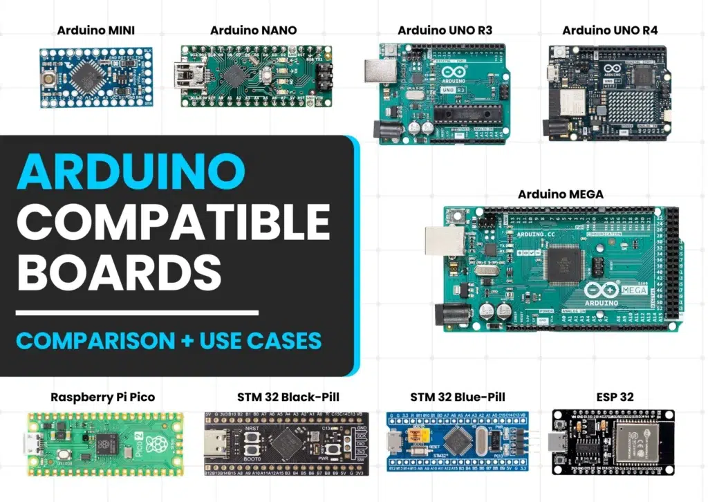
The Arduino Uno R3 board uses the ATmega328P microcontroller and offers:
- 14 Digital I/O Pins
- 6 Analog Input Pins
- Multiple power pins
- Communication pins (UART, I2C, SPI)
 4")
Image Credit: arduino.cc
Power Pins (Top Left Section of Arduino Uno Pin Diagram)
These pins handle the board’s power input and output.
| Pin | Function |
|---|---|
| VIN | Connect 7–12V DC power adapter |
| 5V | Main 5V output to sensors/modules |
| 3.3V | Low power sensors (3.3V output) |
| GND | Ground (0V reference) |
| RESET | Manually restart your Arduino |
Tip: Never supply voltage through both USB and VIN at the same time.
 5")
Digital Pins (D0–D13) in Arduino Uno Pin Diagram
Digital pins work with either HIGH (5V) or LOW (0V) states. According to the Arduino Uno pin diagram, these are used for:
- LED blinking
- Reading button presses
- Controlling motors, buzzers
Special Pins:
- D0 (RX) & D1 (TX): Used for serial communication with PC
- PWM Pins: D3, D5, D6, D9, D10, D11 (marked with ~ symbol)
digitalWrite(13, HIGH); // Turn on LED
If you look at the official Arduino Uno pin diagram, you’ll notice these pins are clearly marked for ease of use.
PWM Pins (~) – Analog-Like Output
PWM (Pulse Width Modulation) pins allow simulated analog output, used for:
- Dimming LEDs
- Speed control of DC motors
- Sound modulation
analogWrite(6, 128); // 50% duty cycle (half brightness)
Exciting Introduction to Arduino: A Beginner’s Guide (2025 Edition)Exciting Introduction to Arduino: A Beginner’s Guide (2025 Edition)
Analog Input Pins (A0–A5) – Arduino Uno Pin Diagram Section
These pins read analog voltages (0–5V) and convert them into values from 0 to 1023.
Common uses:
- Temperature sensors
- LDRs (Light sensors)
- Potentiometers
int val = analogRead(A0);
These analog pins are located on the left side of the Arduino Uno pin diagram.
Bonus: These can also be used as digital pins!
Communication Pins in Arduino Uno Pin Diagram
1. Serial (UART) – D0, D1
Used to communicate with your computer via USB.
2. SPI – D10 to D13
Used for high-speed communication with:
- SD cards
- Displays
- Sensors
3. I2C – A4 (SDA), A5 (SCL)
Perfect for multiple devices using only 2 wires (e.g., OLEDs, Accelerometers)
#include <Wire.h>
Wire.begin(); // Starts I2C communication
When looking at the Arduino Uno pin diagram, these communication pins are often grouped for quick reference.
AREF Pin
AREF (Analog Reference) pin is used to set custom voltage reference for analog readings.
- Helps in increasing accuracy when working with lower voltage sensors.
- Must use
analogReference(EXTERNAL);in code.
Note: Leave unused if you’re unsure.
AREF can be seen at the top-right corner of most Arduino Uno pin diagrams.
Summary Table – Arduino Uno Pin Diagram Quick View
| Pin Type | Count | Use Case |
|---|---|---|
| Digital I/O | 14 | LEDs, buttons, motors |
| PWM | 6 | Dimming, speed control |
| Analog Inputs | 6 | Sensor data |
| Power Pins | 5+ | Power IN/OUT |
| Communication | 6+ | UART, SPI, I2C |
Arduino Uno Pin Diagram – FAQ
🔸 What is the use of the Arduino Uno pin diagram?
It helps beginners and pros connect components correctly and avoid mistakes.
🔸 How do I know which pin to use for PWM?
PWM pins are marked with ~ symbol. Common ones: D3, D5, D6, D9, D10, D11.
🔸 Can I power Arduino Uno with a battery?
Yes, use the VIN pin for 7–12V batteries.
🔸 What is the use of the AREF pin?
To provide an external reference voltage for precise analog readings.
🔸 Are analog pins only for input?
No, analog pins A0–A5 can also be used as digital I/O.
🔸 Where can I find a reliable Arduino Uno pin diagram?
You can view it on the official Arduino site or refer to this detailed guide.
More Advanced Tips (Optional Reading)
- You can use interrupts on pins D2 and D3 to trigger actions on events like sensor changes.
- Use
pinMode()properly to avoid errors and undefined behaviors. - When using multiple modules, always double-check power compatibility and communication protocols.